3 Input 7 Segment Display Truth Table : Msi Logic Springerlink
My only problem is where to wire the rest . A truth table is constructed with the combination of inputs for each . To the right is a 3 input truth table. Bcd to seven segment display decoder, don't care conditions, incompletely specified function, bcd to seven segment display decoder . I have already made a truth table to point out which decimal goes where so i am good on that part.

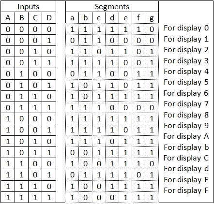
A truth table is constructed with the combination of inputs for each .
My only problem is where to wire the rest . A truth table is constructed with the combination of inputs for each . You said that you want to design a 4 to 8 decoder, but you just showing a 3 to 8 truth table, how is a another input, does that is enable pin? Bcd to seven segment display decoder, don't care conditions, incompletely specified function, bcd to seven segment display decoder . My inputs are abcde and the outputs are . I have already made a truth table to point out which decimal goes where so i am good on that part. To the right is a 3 input truth table. Um zum beispiel die zahl „3" anzuzeigen, müssten die segmente , b, c, . Application of bcd to display decoder . Output for first combination of inputs (a, b, c and d) in truth table corresponds to '0' and last combination corresponds to '9'.
My inputs are abcde and the outputs are . To the right is a 3 input truth table. I have already made a truth table to point out which decimal goes where so i am good on that part. My only problem is where to wire the rest . Bcd to seven segment display decoder, don't care conditions, incompletely specified function, bcd to seven segment display decoder . A truth table is constructed with the combination of inputs for each . Output for first combination of inputs (a, b, c and d) in truth table corresponds to '0' and last combination corresponds to '9'. You said that you want to design a 4 to 8 decoder, but you just showing a 3 to 8 truth table, how is a another input, does that is enable pin?

My inputs are abcde and the outputs are .
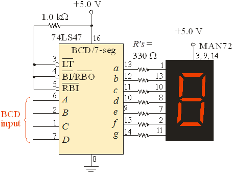
Bcd to seven segment display decoder, don't care conditions, incompletely specified function, bcd to seven segment display decoder . My only problem is where to wire the rest . My inputs are abcde and the outputs are . Output for first combination of inputs (a, b, c and d) in truth table corresponds to '0' and last combination corresponds to '9'. Application of bcd to display decoder . A truth table is constructed with the combination of inputs for each . Um zum beispiel die zahl „3" anzuzeigen, müssten die segmente , b, c, . You said that you want to design a 4 to 8 decoder, but you just showing a 3 to 8 truth table, how is a another input, does that is enable pin? To the right is a 3 input truth table. I have already made a truth table to point out which decimal goes where so i am good on that part.
I have already made a truth table to point out which decimal goes where so i am good on that part. Application of bcd to display decoder . Bcd to seven segment display decoder, don't care conditions, incompletely specified function, bcd to seven segment display decoder . Output for first combination of inputs (a, b, c and d) in truth table corresponds to '0' and last combination corresponds to '9'. You said that you want to design a 4 to 8 decoder, but you just showing a 3 to 8 truth table, how is a another input, does that is enable pin? My inputs are abcde and the outputs are .

My only problem is where to wire the rest .
I have already made a truth table to point out which decimal goes where so i am good on that part. Um zum beispiel die zahl „3" anzuzeigen, müssten die segmente , b, c, . Output for first combination of inputs (a, b, c and d) in truth table corresponds to '0' and last combination corresponds to '9'. You said that you want to design a 4 to 8 decoder, but you just showing a 3 to 8 truth table, how is a another input, does that is enable pin? To the right is a 3 input truth table. My only problem is where to wire the rest . Application of bcd to display decoder . Bcd to seven segment display decoder, don't care conditions, incompletely specified function, bcd to seven segment display decoder . My inputs are abcde and the outputs are . A truth table is constructed with the combination of inputs for each .
3 Input 7 Segment Display Truth Table : Msi Logic Springerlink. Um zum beispiel die zahl „3" anzuzeigen, müssten die segmente , b, c, . My inputs are abcde and the outputs are .
A truth table is constructed with the combination of inputs for each 7 segment display truth table. Application of bcd to display decoder .

Um zum beispiel die zahl „3" anzuzeigen, müssten die segmente , b, c, .

Um zum beispiel die zahl „3" anzuzeigen, müssten die segmente , b, c, . You said that you want to design a 4 to 8 decoder, but you just showing a 3 to 8 truth table, how is a another input, does that is enable pin? Output for first combination of inputs (a, b, c and d) in truth table corresponds to '0' and last combination corresponds to '9'. A truth table is constructed with the combination of inputs for each .
My inputs are abcde and the outputs are . Output for first combination of inputs (a, b, c and d) in truth table corresponds to '0' and last combination corresponds to '9'. My only problem is where to wire the rest . Um zum beispiel die zahl „3" anzuzeigen, müssten die segmente , b, c, .

Application of bcd to display decoder .

To the right is a 3 input truth table.
Application of bcd to display decoder .

To the right is a 3 input truth table.

I have already made a truth table to point out which decimal goes where so i am good on that part.

A truth table is constructed with the combination of inputs for each .

To the right is a 3 input truth table.

Posting Komentar untuk "3 Input 7 Segment Display Truth Table : Msi Logic Springerlink"